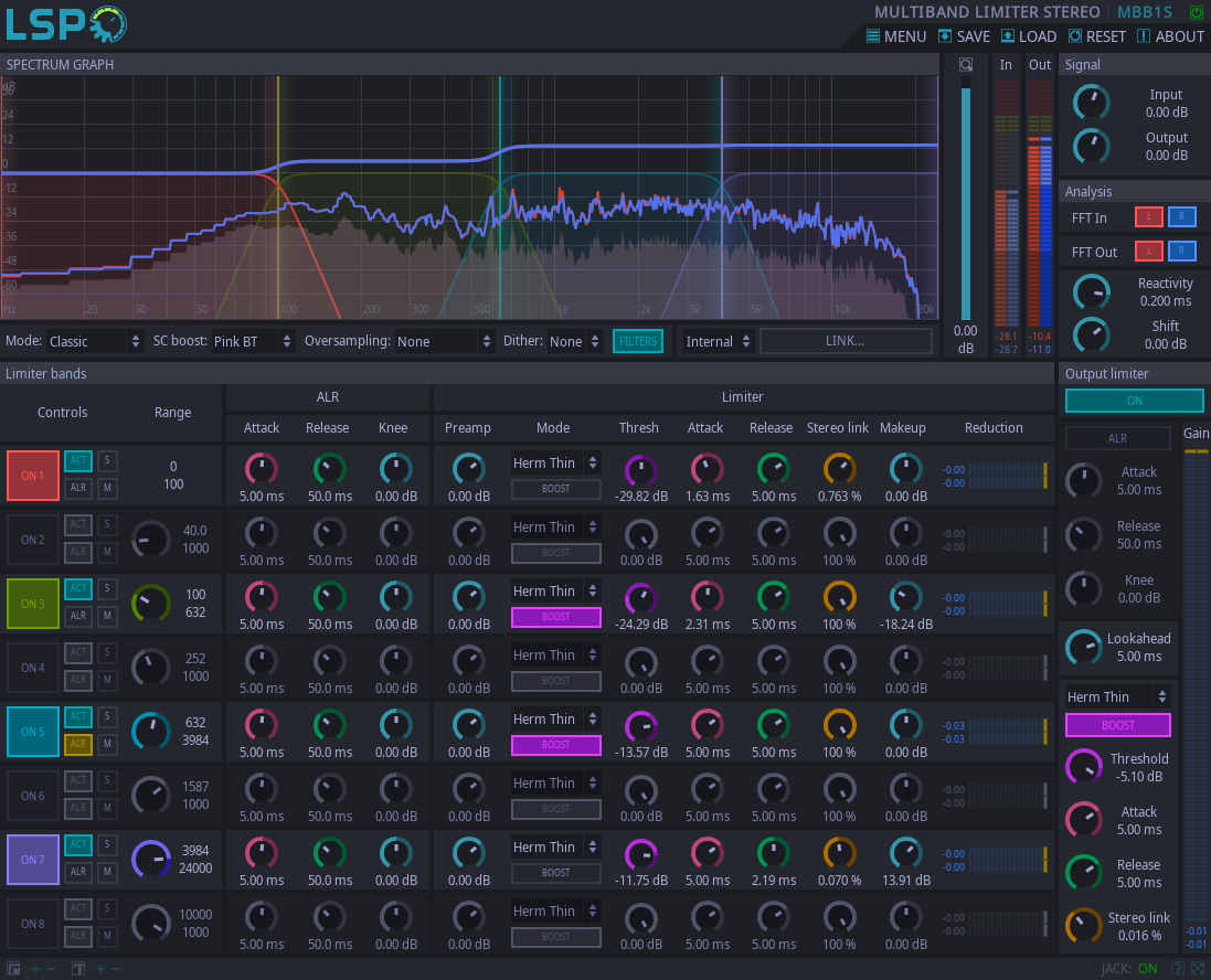
Multiband Limiter Stereo

Detailed: LSP Multiband Limiter Stereo (MBB1S)
Formats: CLAP, JACK, LADSPA, LV2, VST2, VST3
Categories: Limiter
Developer: Vladimir Sadovnikov
Description:
This plugin introduces a multiband limiter with flexible configuration. In most cases it acts as a brick-wall limiter but there are several settings for which is acts as an compressor with extreme settings, so the output signal may exceed the limiter's threshold. It prevents input monosignal from raising over the specified Threshold.
Attention: this plugin implements set of limiting modes, most of them are iterative. That means that CPU load may be not stable, in other words: the more work should be done, the more CPU resources will be used. Beware from extreme settings.
The gain reduction algorithm consists of four stages:
- Per frequency band automated level regulation.
- Per frequency band brickwall gain reduction.
- Per mix automated level regulation.
- Per mix band brickwall gain reduction.
That means that plugin provides per frequency band limiting algorithm and post-limiting after all frequency bands become summed together.
- Automated Level Regulation (ALR) acts like a compressor with infinite ratio for purpose of estimating the smoothed gain reduction level. The gain reduction level is controlled by the envelope of the signal applied to the compressor's gain reduction curve. The smoothness of the envelope is controlled by the Attack and Release knobs in the ALR section. Since different signals have different envelopes with short release time, the Knee knob allows to adjust the threshold of the compressor. Adjusting Knee may give possibility to gain some additional decibels of loudness in the final result.
- Peak cutting algorithm which searches peaks above the threshold values and applies short gain reduction patches to the signal. The form of patch is controlled by the Mode selector and it's length is controlled by the corresponding Attack and Release knobs. Note that Lookahead also affects these values: Attack can not be larger than Lookahead and Release can not be twice larger as Lookahead. Setting these values larger than allowed automatically makes them considered to be set to maximum possible values.
- Unlike classic crossovers which use IIR (Infinite Impulse Response) filters to split signal into multiple bands and shift the phase of the audio signal at band split points, the Linear Phase allows to use FIR (Finite Impulse Response) filters which are deprived of this.
- Unlike most IIR filters which are designed using bilinear transform, linear phase filters allow to simulate their tranfer function to look like the transfer function of analog filters, without deforming it's magnitude envelope near the nyquist frequency.
- Unlike design of classic Linkwitz-Riley filters, the design of IIR filters provides shorter transition zone of the filter.
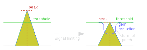
Simplified peak processing example is shown on the following picture:

Of course, the output signal does not repeat the envelope form of input signal because it's amplitude is changed smoothly, so in fact the form of output signal is more complicated.
Currently there are three forms of patches applied to the gain curve - hermite (using cubic polynom for interpolation transients), exponential and linear. These forms can be explained with following picture:

Gain reduction patch affects not only the peak sample, but also surrounding samples. The position and form of this interpolation is related to the peak, so there are four different variants of patch envelope - thin, tail, duck and wide. All these forms related to the peak are shown on the following picture:

On this image, sloping lines mean the transision part of the patch. The flat cap in the middle before the peak is a half of attack time, the flat cap in the middle after the peak is a half of release time. Also it's obvious that different envelope forms differently affect dynamics of the signal.
Controls:
- Bypass - bypass switch, when turned on (led indicator is shining), the plugin bypasses signal.
- Mode - combo box that allows to switch between the following modes:
- Classic - classic operating mode using IIR filters and allpass filters to compensate phase shifts.
- Linear Phase - linear phase operating mode using FFT transform (FIR filters) to split signal into multiple bands, introduces additional latency.
- SC Boost - enables addidional boost of the sidechain signal:
- None - no sidechain boost is applied.
- Pink BT - a +3db/octave sidechain boost using bilinear-transformed shelving filter.
- Pink MT - a +3db/octave sidechain boost using matched-transformed shelving filter.
- Brown BT - a +6db/octave sidechain boost using bilinear-transformed shelving filter.
- Brown MT - a +6db/octave sidechain boost using matched-transformed shelving filter.
- Oversampling - oversampling mode:
- None - oversampling is not used.
- Half 2x/16 bit - 2x Lanczos oversampling of Sidechain signal with 16-bit precision of output samples.
- Half 2x/24 bit - 2x Lanczos oversampling of Sidechain signal with 24-bit precision of output samples.
- Half 3x/16 bit - 3x Lanczos oversampling of Sidechain signal with 16-bit precision of output samples.
- Half 3x/24 bit - 3x Lanczos oversampling of Sidechain signal with 24-bit precision of output samples.
- Half 4x/16 bit - 4x Lanczos oversampling of Sidechain signal with 16-bit precision of output samples.
- Half 4x/24 bit - 4x Lanczos oversampling of Sidechain signal with 24-bit precision of output samples.
- Half 6x/16 bit - 6x Lanczos oversampling of Sidechain signal with 16-bit precision of output samples.
- Half 6x/24 bit - 6x Lanczos oversampling of Sidechain signal with 24-bit precision of output samples.
- Half 8x/16 bit - 8x Lanczos oversampling of Sidechain signal with 16-bit precision of output samples.
- Half 8x/24 bit - 8x Lanczos oversampling of Sidechain signal with 24-bit precision of output samples.
- Full 2x/16 bit - 2x Lanczos oversampling of Sidechain signal and Input signal with 16-bit precision of output samples.
- Full 2x/24 bit - 2x Lanczos oversampling of Sidechain signal and Input signal with 24-bit precision of output samples.
- Full 3x/16 bit - 3x Lanczos oversampling of Sidechain signal and Input signal with 16-bit precision of output samples.
- Full 3x/24 bit - 3x Lanczos oversampling of Sidechain signal and Input signal with 24-bit precision of output samples.
- Full 4x/16 bit - 4x Lanczos oversampling of Sidechain signal and Input signal with 16-bit precision of output samples.
- Full 4x/24 bit - 4x Lanczos oversampling of Sidechain signal and Input signal with 24-bit precision of output samples.
- Full 6x/16 bit - 6x Lanczos oversampling of Sidechain signal and Input signal with 16-bit precision of output samples.
- Full 6x/24 bit - 6x Lanczos oversampling of Sidechain signal and Input signal with 24-bit precision of output samples.
- Full 8x/16 bit - 8x Lanczos oversampling of Sidechain signal and Input signal with 16-bit precision of output samples.
- Full 8x/24 bit - 8x Lanczos oversampling of Sidechain signal and Input signal with 24-bit precision of output samples.
- Dither - enables some dithering noise for the specified output amplitude quantization bitness.
- Zoom - zoom fader, allows to adjust zoom on the frequency chart.
- Sidechain Source - allows to set the sidechain source
- Internal - the audio inputs of plugin are used as sidechain signal.
- Link - the shared memory link is used to receive sidechain signal.
- Link - the name of shared memory link used to receive sidechain signal
- Zoom - zoom fader, allows to adjust zoom on the frequency chart.
- In - the input signal meter.
- Out - the output signal meter.
'Signal' section:
- Input - the amount of gain applied to the input signal before processing.
- Output - the amount of gain applied to the output signal before processing.
'Analysis' section:
- FFT In - enables FFT curve graph of input signal on the spectrum graph.
- FFT Out - enables FFT curve graph of output signal on the spectrum graph.
- Reactivity - the reactivity (smoothness) of the spectral analysis.
- Shift - allows to adjust the overall gain of the analysis.
'Limiter bands' section:
- Controls - overall controls over the band:
- ON - enables the specific band.
- ACT - enables the limiter on the specific band and can be used for quick A/B test for the specific band.
- ALR - enables ALR (Automatic Level Regulation) for the specific band.
- S - enables solo mode for the specific band.
- M - mutes the specific band.
- Range - the knob that allows to set up the start frequency for corresponding band and view it's frequency range.
- ALR - ALR (Automatic Level Regulation) settings for the specific band:
- Attack - the attack time of the ALR compressor.
- Release - the release time of the ALR compressor.
- Knee - the knee of the ALR compressor.
- Limiter - limiter settings for the specific band:
- Preamp - the pre-amplification of the sidechain signal.
- Mode - the operating mode of the specific limiter:
- Herm Thin, Herm Wide, Herm Tail, Herm Duck - hermite-interpolated cubic functions are used to apply gain reduction.
- Exp Thin, Exp Wide, Exp Tail, Exp Duck - exponent-interpolated functions are used to apply gain reduction.
- Line Thin, Line Wide, Line Tail, Line Duck - linear-interpolated functions are used to apply gain reduction.
- Boost - applies corresponding to the Threshold gain to the band's output signal.
- Thresh - the maximum input level of the signal allowed by limiter.
- Attack - the attack time of the limiter. Can not be greater than Lookahead time (greater values are truncated) for some modes.
- Release - the attack time of the limiter. Can not be twice greater than Lookahead time (greater values are truncated) for some modes.
- Makeup - the makeup gain applied after the limiter stage.
- Reduction - the overall gain reduction meter.
'Output Limiter' section:
- ON - Enables the output limiter.
- ALR - Enables the ALR (Automatic Level Regulation) for the output limiter:
- Attack - the attack time of the ALR compressor.
- Release - the release time of the ALR compressor.
- Knee - the knee of the ALR compressor.
- Lookahead - the size of lookahead buffer in milliseconds. Forces the limiter to add the corresponding latency to output signal.
- Mode - the operating mode of the output limiter:
- Herm Thin, Herm Wide, Herm Tail, Herm Duck - hermite-interpolated cubic functions are used to apply gain reduction.
- Exp Thin, Exp Wide, Exp Tail, Exp Duck - exponent-interpolated functions are used to apply gain reduction.
- Line Thin, Line Wide, Line Tail, Line Duck - linear-interpolated functions are used to apply gain reduction.
- Boost - applies corresponding to the Threshold gain to the band's output signal.
- Threshold - the maximum output level of the signal allowed by the limiter.
- Attack - the attack time of the limiter. Can not be greater than Lookahead time (greater values are truncated) for some modes.
- Release - the attack time of the limiter. Can not be twice greater than Lookahead time (greater values are truncated) for some modes.


