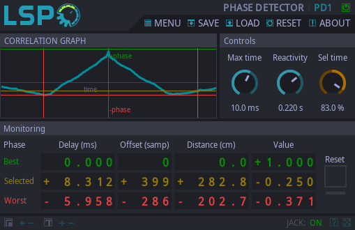
Phase Detector

Detailed: LSP Phase Detector (PD1)
Formats: CLAP, JACK, LADSPA, LV2, VST2, VST3
Categories: Analyser
Developer: Vladimir Sadovnikov
Description:
This plugin allows to detect phase between two sources. For example, for two or more microphones set at the different positions and distances from the sound source.
The internal algorithm is based on correlation function calculation between two sources.
Be aware: because there are many correlation functions for different phases calculated at one time, the entire analyzing process can take a lot of CPU resources. You can also reduce CPU utilization by lowering the maximum analysis time.
The plugin bypasses input signal without any modifications, so it can be placed everywhere it's needed.
Controls:
- Bypass - bypass switch, when turned on (led indicator is shining), the analyser doesn't do anything. After the bypass is turned off, the state of analyser will be automatically reset.
- Max time - maximum analysis time. Sets maximum time interval of phase analysis. Note that analysis shows both negative and positive time offsets, so the actual analysis time is twice greater than the value set by this control. The state of analyser will be automatically reset on change of this control.
- Reactivity - the parameter that allows to configure how the correlation function value reacts on the correlation function change. Is similar to the case when each individual curve of the correlation function is passed thru the lowpass filter. The lesser reactivity value causes less stable correlation graph but gives more tolerance and vice verse.
- Sel time - the custom time selected for metering. Actually is the amount in percent (%) of the maximum analysis time. The metering values for this parameter are colored with yellow in monitoring section.
- Reset - this control allows to immediately reset the state of analyser.
Meters:
- Best - row of the monitoring section, displays values for the best detected phase that gives the best value from the correlation function set.
- Selected - row of the monitoring section, displays values for the Sel time parameter that give the value of correlation function at the selected time.
- Worst - row of the monitoring section, displays values for the worst detected phase that gives the worst value from the correlation function set.
- Delay - column of the monitoring section, displays the time difference between two input channels for the correlation function value.
- Offset - column of the monitoring section, displays the sample difference between two input channels for the correlation function value.
- Distance - column of the monitoring section, displays the relative to the sound speed distance difference between two input channels for the correlation function value.
- Value - column of the monitoring section, displays the normalized value of the correlation function.
The Correlation Graph is two-dimensional graph that allows to monitor immediate values of the set of correlation functions. The horizontal axis is the relative time offset, the vertical axis is the normalized correlation function value. The thick blue line shows the normalized values of the set of correlation functions depending on the time offset. The values of the Best, Selected and Worst meters are drawn as crossing lines with the matching colors.
When the signal from the left (A) channel comes with delay relatively to the right (B) channel, the offset values will be positive. When the signal from the B channel comes with delay relatively to the A, the offset values become negative. In most cases, when sources are in phase, the Value indicator for the Best row takes the value near to 1, otherwise the Value indicator of the Worst row takes value near to -1, so for correctly phasing two sources the phase for one of the sources has to be inverted. Two sources are in-phase when the Value of the Best row shows 1 and other columns (especially Offset) show the values near to the 0 the most time.


